
Openstack Networking for Scalability and Multi-tenancy with VlanManager
In a previous post I explained the basic mode of network operation for OpenStack, namely FlatManager and its extension, FlatDHCPManager. In this post, I'll talk about VlanManager. While flat managers are designed for simple, small scale deployments, VlanManager is a good choice for large scale internal clouds and public clouds. As its name implies, VlanManager relies on the use of vlans ("virtual LANs"). The purpose of vlans is to partition a physical network into distinct broadcast domains (so that host groups belonging to different vlans can't see each other). VlanManager tries to address two main flaws of flat managers, those being:
- lack of scalability (flat managers rely on a single L2 broadcast domain across the whole OpenStack installation)
- lack of proper tenant isolation (single IP pool to be shared among all the tenants)
In this post I will focus on VlanManager using multi-host network mode in OpenStack. Outside the sandbox, this is considered safer than using single-host mode, as multi-host does not suffer from the SPOF generated by running a single instance of a nova-network daemon per an entire openstack cluster. However, using VlanManager in single-host mode is in fact possible. (More about multi-host vs single-host mode can be found here).
Difference between "flat" managers and VlanManager
With flat managers, the typical administrator’s workflow for networking is as follows:
- Create one, large fixed ip network (typically with 16-bit netmask or less) to be shared by all tenants:
nova-manage network create --fixed_range_v4=10.0.0.0/16 --label=public
- Create the tenants
- Once tenants spawn their instances, all of them are assigned whatever is free in the shared IP pool.
So typically, this is how IPs are allocated their instances in this mode:
tenant_1:

tenant_2:

We can see tenant_1 and tenant_2 instances have landed on the same IP network, 10.0.0.0.
With VlanManager, the admin workflow changes:
- Create a new tenant and note its tenantID
- Create a dedicated fixed ip network for the new tenant:
nova-manage network create --fixed_range_v4=10.0.1.0/24 --vlan=102 \
 --project_id="tenantID"
- Upon spawning, tenant's instance will automatically be assigned an IP from tenant's private IP pool.
So, compared to FlatDHCPManager, we additionally define two things for the network:
- Associate the network with a given tenant (
--project_id=<tenantID>). This way no one else than the tenant can take IPs from it. - Give this network a separate vlan (
--vlan=102).
From now on, once a tenant spawns a new vm, it will automatically get the address from his dedicated pool. It will also be put on a dedicated vlan which OpenStack will automatically create and maintain. So if we created two different networks for two tenants, the situation will look like this:
tenant_1:

tenant2:

It can be clearly seen that tenants' instances have landed on different IP pools. But how are vlans supported?
How VlanManager configures networking
VlanManager does three things here:
- Creates a dedicated bridge for the tenant’s network on the compute node.
- Creates a vlan interface on top of compute node’s physical network interface eth0.
- Runs and configures dnsmasq process attached to the bridge so that the tenant’s instance can boot from it.
Let's suppose that the tenant named “t1” spawns its instance t1_vm_1. It lands on one of the compute nodes. This is how the network layout looks:
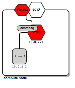
We can see that a dedicated bridge named “br102” has been created along with a vlan interface “vlan102”. Also a dnsmasq process has been spawned and is listening on address 10.0.2.1. Once instance t1_vm_1 boots up, it receives its address from the dnsmasq based on a static lease (please see this previous post on the details of how dnsmasq is managed by OpenStack).
Now, let’s assume now that tenant “t1” spawns another instance named t1_vm_2, and it happens to land on the same compute node as the instance previously created:
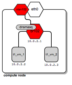
Both instances end up being attached to the same bridge, since they belong to the same tenant, and thus they are placed on the same dedicated tenant’s network. They also get their DHCP configuration from the same dnsmasq server.
Now let’s say that tenant “t2” spawns his first instance. It also lands on the same compute node as tenant “t1”. Also, for his network, a dedicated bridge, vlan interface and dnsmasq are configured:

So it turns out that depending on the number of tenants, this is a normal situation where you have quite a large number of network bridges and dnsmasq processes, all running within a single compute node.
There's nothing wrong with this, however - OpenStack will manage all of them automatically. Unlike the case of using flat managers, here both tenants’ instances reside on different bridges which are not connected to each other. This ensures traffic separation on L2 level. In case of tenant “t1”, the ARP broadcasts sent over br102 and then through to vlan102 are not visible on br103 and vlan103, and vice versa.
Support for tenant networks across multiple compute nodes
So far, we've talked about how this plays out on a single compute node. Most likely, you'll probably use a lot more than one compute node. Usually we want to have as many of them as possible. Then, likely, tenant "t1" instances will be scattered among many compute nodes. This means that his dedicated network must also be spanned across many compute nodes. Still it will need to meet two requirements:
- t1's instances residing on different physical compute nodes must communicate
- t1's network spanning multiple compute nodes must be isolated from other tenants' networks
Typically, compute nodes are connected to a network switch by a single cable. We want multiple tenants to share this link in a way that they don't see one another's traffic.
There is a technology that addresses this requirement called Vlan tagging. Technically, it extends each Ethernet frame by adding a 12-bit field called VID (Vlan ID), which bears the vlan number. Frames bearing an identical Vlan tag belong to a single L2 broadcast domain; thus devices whose traffic is tagged with the same Vlan ID can communicate.
It should be obvious, then, that one can isolate tenants' networks by tagging them with different Vlan IDs.
How does this work in practice? Let us look at the above diagrams.
Traffic for tenant “t1” leaves the compute node via "vlan102". Vlan102 is a virtual interface connected to eth0. Its sole purpose is to tag frames with a vlan number "102", using the 802.1q protocol.
Traffic for tenant “t2” leaves the compute node via "vlan103", which is tagged with vlan tag 103. By bearing different vlan tags, "t1's" traffic will in no way interfere with “t2’s” traffic.
They are unaware of each other, even though they both use the same physical interface eth0 and, afterwards, the switch ports and backplane.
Next, we need to tell the switch to pass tagged traffic over its ports. This is done by putting a given switch port into “trunk” mode (as opposed to “access” mode, which is the default). In simple words, trunk allows a switch to pass VLAN-tagged frames; more information on vlan trunks can be found in this article. At this time, configuring the switch is the duty of the system administrator. Openstack will not do this automatically. Not all switches support vlan trunking. It's something you need to look out for prior to procuring the switch you'll use.
Also - if you happen to use devstack + virtualbox to experiment with VlanManager in a virtual environment, make sure you choose "PCNET - Fast III" as the adapter to connect your vlan network.
Having done this, we come to this model of communication:
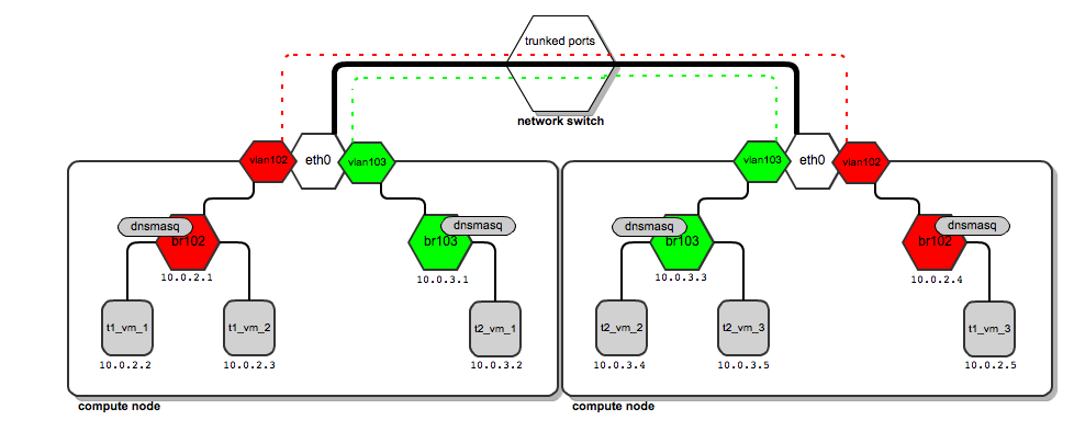
The thick black line from compute nodes to the switch is a physical link (cable). On top of the same cable, vlan traffic tagged by both 102 and 103 is carried (red and green dashed lines). There is no interference in traffic (the two lines never cross).
So how does the traffic look when tenant “t1” wants to send a ping from 10.0.2.2 to 10.0.2.5?
- The packet goes from 10.0.2.2 to the bridge br102 and way up to vlan102, where it has the tag 102 applied.
- It goes past the switch which handles vlan tags. Once it reaches the second compute node, its vlan tag is examined.
- Based on the examination, a decision is taken by compute node to put it onto vlan102 interface.
- Vlan102 strips the Vlan ID field off the packet so that it can reach instances (instances don't have tagged interfaces).
- Then it goes down the way through br102 to finally reach 10.0.2.5.
Configuring VlanManager
To configure VlanManager networking in OpenStack, put the following lines into your nova.conf file:
#We point OpenStack to use VlanManager here:
network_manager=nova.network.manager.VlanManager

#Interface on which virtual vlan interfaces will be created:
vlan_interface=eth0

#The first tag number for private vlans
#(in this case, vlan numbers lower than 100 can serve our
#internal purposes and will not be consumed by tenants):
vlan_start=100
Conclusion
VlanManager is by all means the most sophisticated networking model offered by OpenStack now. L2 scalability and inter-tenant isolation have been addressed.
Nevertheless, it still has its limitations. For example, for each tenant network it relates ip pools (L3 layer) to vlans (L2 layer) (remember? - each tenant's network is identified by a pair of ip pool + vlan). So it is not possible to have two different tenants use the same ip addressing schemes independently in different L2 domains.
Also - vlan tag field is only 12 bits long, which tops out at only 4096 vlans. That means you can have no more than 4096 potential tenants, not that many at cloud scale.
These limitations are yet to be addressed by emerging technologies such as Quantum, the new network manager for OpenStack and software-defined networking.
In the next post in this continuing series, I will give an explanation of how floating ips work.

